Rev A rework: 10 kΩ in series with the sixteen address-path drivers
The same operation as
the eight data-bus drivers, sixteen more times, on parts that
run hotter and are easier to reach. Generated from the board by
tools/make_rework_adh_page.py.
Why
The transform that turned the die's netlist into a board preserved every connection but not every device ratio. Ratioed NMOS needs a weak load against a strong pull-down; the 1,018 depletion loads correctly became 10 kΩ resistors, but 164 VCC-side transistors kept the same BSS138W as the transistor pulling against them — a fair fight where the design needs a rigged one. A contended pair burns about 0.9 W in a package rated for 0.3 W, and leaves a logic “low” at 1–1.9 V against a 1.1–1.5 V switching threshold.
Eight of those were repaired by hand and that repair is confirmed working. These sixteen are the
address-path precharge drivers, and they are worse: they are gated by
cclk, so they contend for a fixed fraction of every cycle rather than a
program-dependent one. Nine of them measured about 80 °C on board #1
with a thermal camera while it executed real code.
adh is the
high byte of the address during a fetch, so a bit that happens to be high is not being pulled low
and does not contend. Over any real run the address sweeps and every bit spends about half its time
low. Confirmed on hardware 2026-08-26 — under a NOP free-run all of them run hot, and
adh6 and adh7 are visibly cycling hot and cold at 3.3 s and
6.6 s at 10 kHz, which is exactly the rate those two PCH bits toggle
(T = 2n × 512 / f).
The sixteen sites
Duty is measured by tools/contention_duty.py, which simulates the board under two
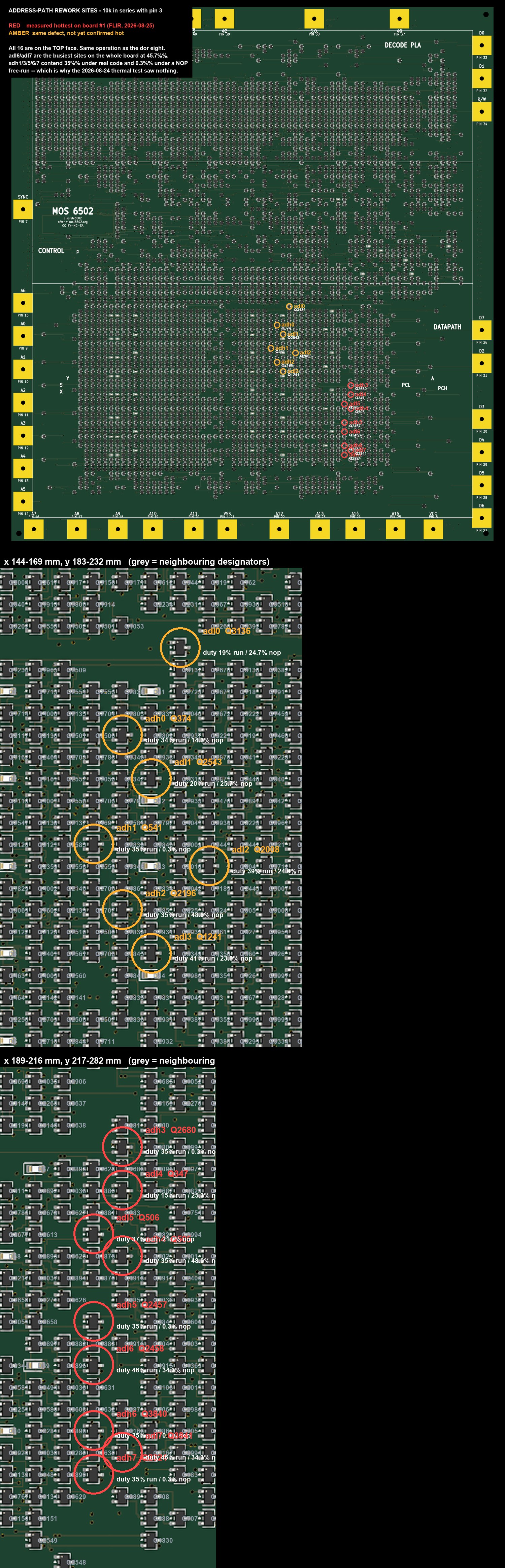
workloads and reports how often each VCC-side device is fighting its pull-down. All sixteen are on
the front face, all are SOT-323, and on all sixteen pin 3 is the VCC
side — the same pin lifted on the data-bus eight.
| net | ref | x (mm) | y (mm) | duty when exercised | R | thermal |
|---|---|---|---|---|---|---|
| adh0 | Q374 | 160.15 | 191.80 | 48% | 10k | — |
| adh1 | Q541 | 156.45 | 205.80 | 48% | 10k | — |
| adh2 | Q2196 | 160.15 | 214.20 | 48% | 10k | — |
| adh3 | Q2680 | 204.55 | 228.20 | 48% | 10k | measured hot |
| adh4 | Q505 | 204.55 | 242.20 | 48% | 10k | measured hot |
| adh5 | Q2457 | 200.85 | 250.60 | 48% | 10k | measured hot |
| adh6 | Q3840 | 200.85 | 264.60 | 48% | 10k | measured hot |
| adh7 | Q2324 | 200.85 | 270.20 | 48% | 10k | measured hot |
| adl0 | Q3136 | 167.55 | 180.60 | 48% | 10k | — |
| adl1 | Q2543 | 163.85 | 197.40 | 48% | 10k | — |
| adl2 | Q2008 | 171.25 | 208.60 | 48% | 10k | — |
| adl3 | Q1241 | 163.85 | 219.80 | 48% | 10k | — |
| adl4 | Q347 | 204.55 | 233.80 | 48% | 10k | measured hot |
| adl5 | Q506 | 200.85 | 239.40 | 48% | 10k | measured hot |
| adl6 | Q2458 | 200.85 | 256.20 | 48% | 10k | measured hot |
| adl7 | Q3841 | 204.55 | 267.40 | 48% | 10k | measured hot |
Same method, and slightly easier
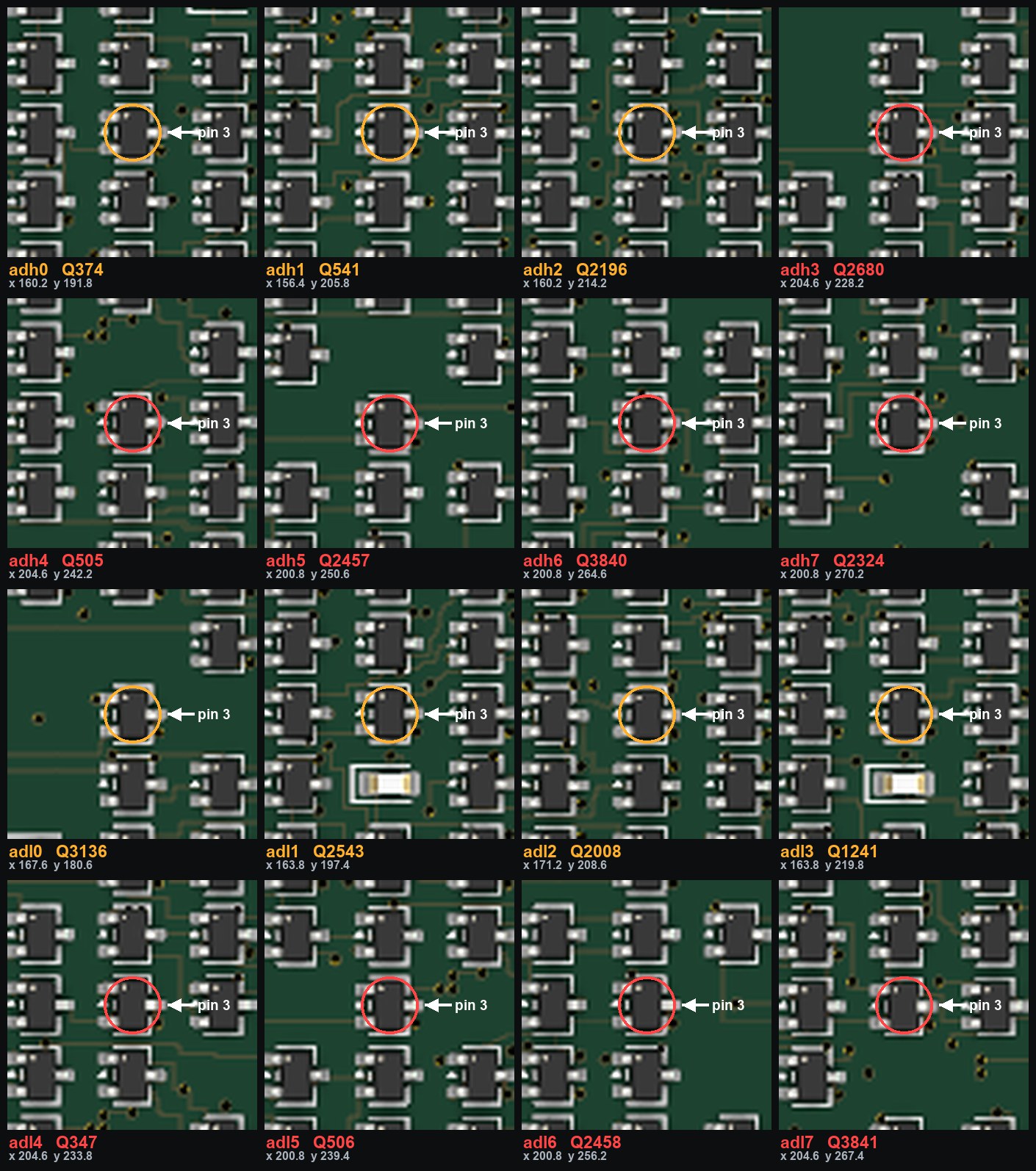
Identical to the data-bus eight: lift pin 3 and bridge it back to its pad with a 10 kΩ resistor. Pin 3 is the lone pin on its side of the SOT-323, 1.78 mm from the other two, so neither neighbour is at risk.
- Value: 10 kΩ on all sixteen (10k). Each of these nets drives
exactly one gate — 27 pF — so the RC rise is about
0.6 µs against a 25 µs half-cycle. This is computed with the same
series_r_for()rule the rev B generator uses, so the hand fix and a future respin cannot drift apart. Do not generalise it:cclkdrives 482 gates and needs 100 Ω. - More room than last time. The nearest neighbouring part is 2.80 mm away, against 1.94 mm at the data-bus sites.
- 0402 is what the board uses (LCSC C25744), but 0603 is easier to handle and there is room for it.
Procedure, per site
Tools: fine-tip iron or hot air, fine tweezers, flux, magnification, a multimeter, and Kapton tape.
- Locate the part. Check the designator against the table and the contact sheet
before touching anything — every neighbour is an identical SOT-323. Note the two
clusters:
adh0–2andadl0–3sit around x 156–171 mm, the rest around x 200–205 mm. - Measure first. Pin 3 to a VCC bond pad should read ~0 Ω. Record it; that is your “before”.
- Lift pin 3. Flux the joint, heat pad 3, lift the leg clear with tweezers and bend it slightly upward. Do not disturb the body.
- Verify the break. The lifted lead to VCC should now read open. If it still reads ~0 Ω the leg is still touching — re-lift.
- Fit the resistor. Tin pad 3, stand the 10 kΩ on end with its lower termination on the pad, solder it, then solder the lifted leg to the upper termination. Put a slip of Kapton tape between the resistor body and the lifted leg, as on the data-bus eight. The leg is springy and a leg that relaxes back shorts the resistor out silently — the board keeps working and simply runs hot again, which is the worst way for a repair to fail.
- Verify the fix. The lifted lead to a VCC bond pad should now read 10 kΩ ± tolerance; pad 3 itself to VCC should still read ~0 Ω.
- Inspect. Resistor clear of pins 1 and 2 and of every neighbour; lifted leg not touching the pad it came from.
Checking it worked
Thermal, not electrical, and take the “before” picture first. Run the CPU on a real program — not NOPs, for the reason above — let it settle two or three minutes, and photograph the two clusters. Repeat after the rework from the same camera position. The nine hot sites should go cold.
The supply current is the blunt version of the same test. Board #1 drew 2.3 A executing before this rework. Note it before you start; a drop of several hundred mA is what success looks like. Do not expect the few-hundred-mA figure early versions of these pages predicted — there are 164 sites with this defect and this fixes sixteen.
Whole-board check. VCC to VSS at the bond pads, read the range-aware way: there is no resistor-only path between the rails, so a few hundred ohms that changes with the meter range is correct and healthy. A fault is under 1 Ω, or a reading that does not move between ranges.
If you are generating a rev B board instead
tools/gen_netlist.py would currently skip 5 of these sixteen:
adl3, adl4, adl5, adl6, adl7. Its has_pulldown test only counts a transistor with vss directly
on a channel pin, and these nets are pulled low through a pass-gate chain instead. They
contend exactly the same way — adl6 and adl7 are the two busiest
sites on the whole board at 45.7% — so a rev B respin generated today would leave the
hottest parts unfixed.
The same flawed test also excluded them from the first duty measurement, until a thermal camera
put them back. Fix has_pulldown to follow conduction paths before trusting rev B's
142-site count.